Original controller for FMS
Connecting the radio transmitter to the personal computer, there is no experience on the midst when it does the FMS, there is no battery of the radio transmitter how says? To designate the remaining amount of the battery as the air while with, because it is not possible, freely to enjoy the FMS which is thought was designated as the original work to do the controller for the FMS. In a word, making the ppm signal, if inserting in the 10pin of the printer connector, because it is excuse, it may become somehow, is.
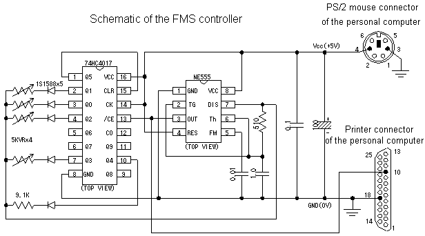
When the schematic is searched with Internet, the exactly good circuit was
found in the below-mentioned home page.
http://www2s.biglobe.ne.jp/~motorize/index.html
When it keeps opening in order in the Reference information -> 2. Original
radi-con device introduction -> 1.Schematic of the transmitter, you can see
the schematic. Because the various schematics have been recorded before in addition
to, one time please try accessing the one which has interest by all means.
With the ppm signal occurrence section of lower half as a reference, the below-mentioned schematic was made. Adjusting to the value of resistance of the stick section of radi-con this time it procures, value of resistance and the condenser is adjusted. It supplies power source from the PS/2 mouse connector of the personal computer. Recently because you think, the person who uses the USB mouse is many PS/2 mouse connectors are the expectation which has been less crowded. PS/2 mouse connectors the male and the female preparing the person who is used PS/2 mouse, both, using the extension cord of PS/2 mouse, relaying this controller please try to connect the mouse. Because the 3pin of PS/2 mouse connectors (the GND) with the 18pin of the printer connector (the GND), it has been connected inside the personal computer, when you make a mistake in wiring of the connector of PS/2 mouse, there is a possibility Vcc (the + 5v) with GND short-circuiting. PS/2 mouse whether the one which makes wiring only of the 4pin is good. As for volume of the stick, the elevator (the ch2), the ladder (the ch1), the throttle (the ch3), the aileron (the ch4) it is connected to order from on the schematic. The one which you would like to adjust to your transmitter please modifies connection.

Note: That much, is not the difficult circuit, but breakdown of the personal computer with error wiring (destruction) it is not the case that it is not either possibility. We ask the one which it challenges , to the last on self responsibility.
[ Parts list ]
|
Item
|
Item name
|
Quantity
|
Remark
|
| IC | 74HC4017 |
1
|
Decimal Johnson counter |
| NE555 |
1
|
Timer IC | |
| Resistance | 9. 1k Ohm |
1
|
_ |
| 510 Ohm |
1
|
_ | |
| Volume | 5k Ohm |
4
|
In the stick section to install |
| Condenser | 0.01 micro |
1
|
_ |
| 0.1 micro |
1
|
_ | |
| 1.0 micro |
1
|
_ | |
| 100 micro |
1
|
Electrolytic condenser (above 10V) | |
| Diode | 1S1588 |
5
|
Switching diode |
| Connector | PS/2 mouse connectors |
1
|
Male (personal computer side female) |
| D - SUB25pin connector |
1
|
Male (personal computer side female) |
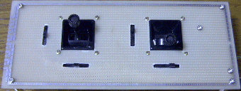
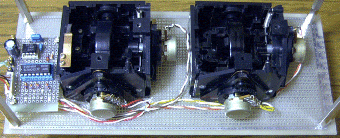
The photo of the controller.
 Top view
 Botom view
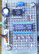
The ppm signal occurrence circuit is just this which passes.

Becoming old, doesn't the one where the transmitter which it stops using sleeps try making the transmitter revive as the FMS controller? However, but we ask to the last on self responsibility.