The PIC interface for FMS2.0beta7
It seems that the user of Windows2000/XP does not have the method of connecting
PUROPO with a printer port, and FMS2.0beta7 cannot connect PUROPO with a printer
port, either, although it thinks that correspondence by FMS2.0beta7 is expected.
In beta 7, the serial interface using the COM port is newly added, in the case
of Windows2000/XP, you will use it. However, it is necessary not using the easy
interface circuit of one transistor but using a microcontroller called PIC to
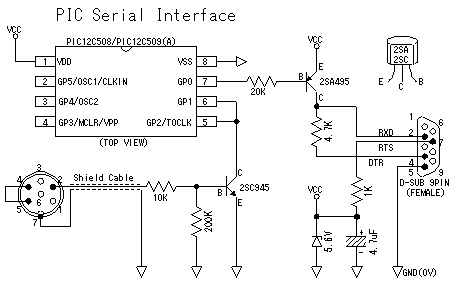
change a PPM signal into the serial signal of RS-232C. Specifically, it becomes
an interface as shown in the following circuit diagrams. Please connect GND
(0V) of a reverse triangular mark, respectively. Moreover, please also connect
VCC (5V) of a round mark, respectively. This circuit drops voltage from the
signal line of RS-232C using a zener diode, and is using it as a power supply.
Before FMS starts, a power supply is not turned on only by putting in the connector
of RS-232C. A power supply is turned on only after FMS starts and reading the
RS-232C signal. Refer to the file FMS_PIC.zip
for programming to PIC.
FMS_PIC.zip:
/firmware/sources/*.* <--- firmware source files
/firmware/12C508.HEX <--- (A) firmware binary for PIC12C508
/firmware/12C509A.HEX <--- (B) firmware binary for PIC12C509A
/firmware.new/sources/*.* <--- firmware.new source files
/firmware.new/12C508.HEX <--- (C) firmware.new binary for PIC12C508
/firmware.new/12C509A.HEX <--- (D) firmware.new binary for PIC12C509A
The contents of the file of (A) and (B) are the same.
The contents of the file of (C) and (D) are the same.
12C508.hex or a 12C509A.hex file is programmed using the PIC writer of marketing
or a their original work. The transmission method of data is only different
and the file of firmware and the file of firmware.new operate normally by both.
as notes at the time of a program -- 12C508.hex/12C509A.hex -- once any program
is a setup of the MCLR terminal OFF and it programs it, reset by the MCLR terminal
will lose its effect Therefore, if it is the specification which takes and reads
a synchronization with a MCLR terminal when reading the program written in with
the PIC writer, a synchronization cannot be taken and normal data cannot be
read. Keep in mind that only the intention of reading when the worst since Vpp
voltage is built when reading data will rewrite data. If a synchronization is
taken by power-on reset using a PIC writer with the ON/OFF function of a power
supply, data can be read also with the MCLR terminal OFF. I think that following
Mr.Ishijima's HP is consulted.
Mr.Ishijima's
homepage(sorry Japanese only)
When you can't make PIC interface(RS-232C/USB)
yourself, you can purchase it by the following webpage.
the Mosquito Moth Laboratory(sorry Japanese
only)

Notes: Although it is not so difficult a circuit, there is the possibility of failure (destruction) of the personal computer by connection mistake. Please challenge on self responsibility.
[Parts list]
|
Item
|
Item name
|
Quantity
|
Remark
|
| IC | PIC12C509(A) |
1
|
PIC(Microcontroller) |
| Transistor | 2SA495 |
1
|
PNP Tr.(2SA733,933,1015,1029,1096) |
| 2SC945 |
1
|
NPN Tr.(2SC372,458,829,1740,1815) | |
| Resistance | 1K Ohm |
1
|
_ |
| 4.7K Ohm |
1
|
_ | |
| 10K Ohm |
1
|
_ | |
| 20K Ohm |
1
|
_ | |
| 200K Ohm |
1
|
_ | |
| Condencer | 4.7uF |
1
|
Electrolytic condenser (above 35V) |
| Diode | 5.6V |
1
|
Zener Diode |
| Connector | DIN6pin |
1
|
Male |
| D-SUB9pin |
1
|
Female |
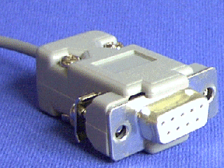
D-SUB 9pin connector
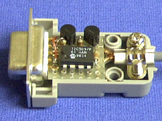
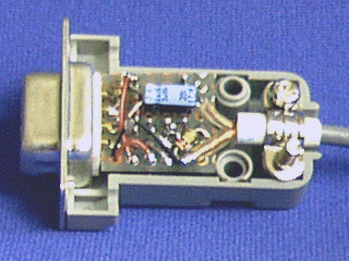
All interface circuits are contained in this small circuit board.
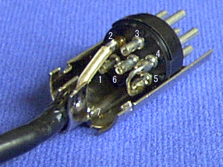
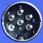
It is the photograph of a PUROPO side connector. Since it numbered to prevent
mistakes, please see together with a circuit diagram.
A setup of the serial interface by the side of a personal computer
is performed as follows.
A control panel is opened -> A system is double-clicked -> Hardware is
chosen -> A device manager is clicked. -> + mark beside a port is clicked
-> The communication port (COM1 or COM2) to be used is double-clicked ->
A setup of a port is clicked. If the setting screen of a port comes out, it
will be made a setup of 19200bps, 8 bits, non-parity, one stop bit, and no flow
control, and O.K. is clicked.
A setup of the controller by the side of FMS is performed as follows.

Controls->Analog control ... is clicked
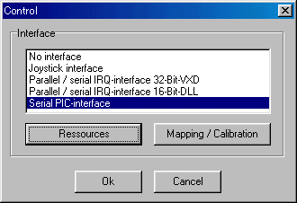
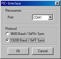
Serial PIC-interface is chosen and Ressources is clicked. Choosing a port, Protocol
chooses 19200 Baud / 0xFF Sync.
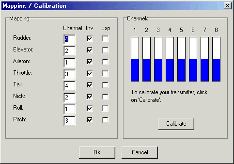
Mapping/Calibration is clicked and A calibration and mapping are set up.
At the last, Let's enjoy FMS.